R2build
system is a tool/framework to establish your daily build(or
nightly build, or build automation, or continuous integration system) in a very
easy way . It includes, but is not limited to, plug-ins for email notification,
FTP, various installer packaging tool, Java/C++/Ant/Nant/.Net/Delphi/C++Builder,
and various source control tools.
R2Build is licensed
under the terms of the GNU General Public License for Non-commercial software
product build, For Commercial software build, please
contact with R2build@gmail.com to get
approval.
The dashboard
Application manages multiple projects/builds
The R2Build
System application constructs your build flowgraph
and excutes your build flowgraph.
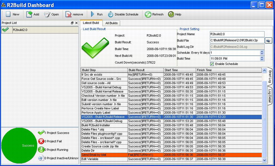
The R2build Dashboard application include the following sub windows:
· Toolbar: you can use toolbar to create a new build, add a new build if you have .r2p file, open and edit the build, remove project from project list, schedule and run the build, etc..
· Project List: keep all the R2build projects, the color and the icon indicate the last build status(Green for success, Red for Fail, and other more colors), in the bottom of the project list, there is a pie chart of the projects(based on the data of last build)
· Latest Build: show the latest build log of the selected project.
· All Builds: Show all the builds logs and the build summary of the current selected project.
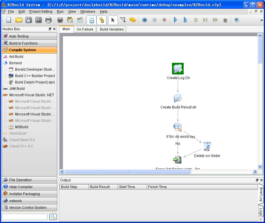
The R2build System
application includes the following sub windows:
Tool Box Window:
contains
most of the development and test tools, including but not limited to:
l
Source control tools: CVS/Perforce/ClearCase/VSS/subversion/Surround
SCM
l
Compiler: Ant/Nant/.Net/Delphi/C++Builder/VC/VB
l
Installer packaging: WISE/InstallShield/NullSoft/Inno
l
Help Compiler
l
File operation
l
Network: FTP/Mail
l
Auto testing tools: WinRunner/QAWizard/Robot/NUnit/
TestComplete
It’s
populated by plug-in configuration xml file (.xml). You can also create your
own plugin xml file to enable a new tool. By draging an icon from the tool box, you can create a new
node in the flowgraph view.
Main Tab(Build flowgraph)
:
The
main build flowgraph includes main build functions, just
like a main function in c++ project. .
A build flowgraph
includes nodes and links. A Node is one build step(for
example a delete file action, or a compile c++ project action), you can add
node by dragging from Tool-Box window onto this canvas, or double click to add
to the tail of the flowgraph, to change the node
parameters, double click the node. You can link two nodes to indicate the
transition after executing node. Using Nodes and Links, you can draw an automation Flowgraph (Build
Settings). You can set one start node for this graph.
On Failure Tab(Build flowgraph):
The “On
Failure” build flowgraph defined the error processing
nodes. When error occurs in the main build flowgraph(also the node does
not ignore the errors, see node parameter setting chapter for more info), then
the “On failure” build flowgraph will be called. An
example is, in the “on failure” build flowgraph, include the cleanup
nodes, also send the build fail notification.
Build Variable Tab:
To
make the build flowgraph more dynamic, you can use
the variables. An good example of variable is: you define the Project source
code dir as SRC_DIR, and then you can use it anywhere in the node parameters($SRC_DIR). If your dir changes, you only need to
change the variable value, other than searching the nodes and change the parameter
one by one. Please use Variable as much as you can. You can add/delete using
“+” or “-” button.
Log Window:
when
you run the automation flow graph, the log will be displayed here, you can
switch between Brief log(shows the brief nodes execution result) and Log detail
(the detail log for one node), by clicking the tab on the right part of the log
window.
Application Tool Bar:
it
include almost all the function, File operation (save/open), Flow graph drawing
tool (Connect Node button, Add Comment Text button), and debug/run tools.
Setup your toolbox after installation
The
most important configuration is setting up all the software tools you need in
R2Build. Select menu: Project Settings->Setup application Paths (or Setup
Application Paths button in the application tool bar).
(You
can also setup the software tool path when using it, if the software path is
not configured, in the main tool box, it’s displayed in italic text, when you
using it, it will popup a dialog , let you choose the
path for this software.)
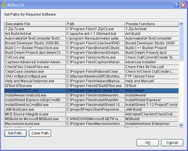
After
you install R2Build, it ships with a default setting for all the required
software tools, but these setting are the default installation locations of these
tools. You should check and set your installed location in R2Build. For
example, for visual source safe, the default installation location is
c:\program files\Microsoft visual studio\common\vss\win32\ss.exe, but if you
installed it to D:\VSS\... on your build server, you should select visual
source safe:ss.exe item in the dialog, double click or click “set path..”
button to choose your dir of ss.exe.
NOTE:
R2Build’s searching rule for tools: when you add the node, R2Build first
searches the tool in the dir you configured, if fail, uses the system PATH env to search again, if still can not find, it will popup a
dialog to let you input the correct path.
Create
a new build project
0. In Rwbuild dashboard, click new to create a new build project.
1. By default,
when you run R2build system application, it will create an empty main/On
Failure build flowgraph for you, you can also Click
the “Create new file” button in the “Application tool bar” to create a new
build flow graph.
2. Setup required
global variable.
In the
Build Variables tab, All the missing required global
variables are marked as red. The
following variable are build in Global variables that must be configured:
·
BUILDLOGFILENAME” is The
log file for this build, this is an important required parameter, also will be
used by dashboard to show the project status, please use full path file name(support variable), an example is
c:\mybuildlogdir\myproject$BUILDNUMBER.txt, all the intermediate log file will
also be stored in the same folder as this file.
· PROJECTNAME: The project name,required parameter, will be displayed in dashboard
· BUILDNUMBER: the integer number to indicate the global build number, Important: you should use edit variable node to increase BUILDNUMBER ( $BUILDNUMBER+1)
You
can add/remove global variables for this build by clicking the “+”, “-” button
in the lower right corner of the build variables tab. To use variable, put a “$”
before the variable name, for example, as the correct format for PROJECTDIR is
“$PROJECTDIR” .
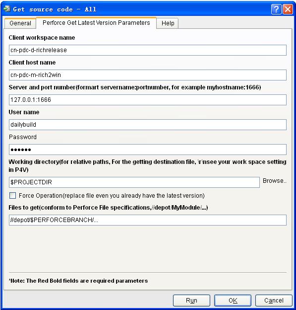
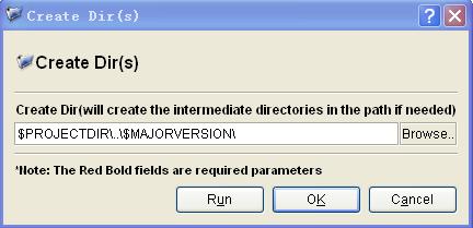
3. Add Build Node:
Drag
and drop an icon in the Tool box (or double click the icon in tool box) to the build flow
graph view, put it in the correct position on the canvas, then double click
this node to set up the parameters of this node. For example, usually, for a
simple build, the first step is getting the latest code from source control
software:
4. Add Link:
After
adding some nodes in the build flow graph view, you can add the transition link
between nodes. Click “add connection” button, select first node, draw a line to
the second node, then release the mouse (just like you draw a line in the MSPaint), the arrow means the direction of transition. You
can also setup the transition condition: double-clicking the line and input the
conditions in the popup “Edit Condition” dialog. For example:
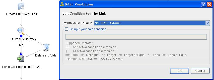
There is a line from “Perforce Get Latest
Version Code” node to “Delete Files” node. Once you set the transition
condition to “return value equal to Success”, then after the task of getting latest
code finishes successfully, the action of “Delete file” occurs.
5. Setup start node:
Start node is the
entrance of the build flow graph. Each graph has one start node. Select a node,
then Click “Set Start Node” button.
6. using the same step as 1~5 to create the "on failure" build flowgraph:
The onfailure build flowgraph is the error processing function, when the there is error in execution of the main build flowgraph
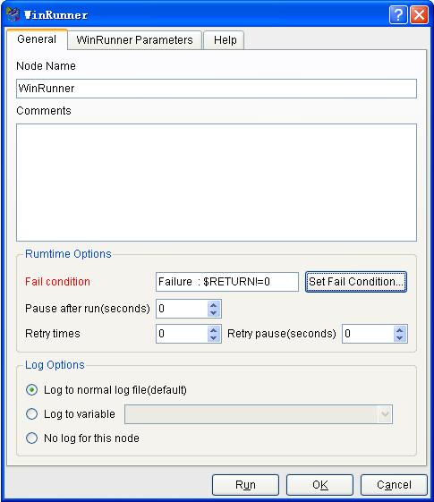
Important note: every node, you can double click to setup the node paramter, in the Genenal tab, you can "set fail condition" for current node, for most cases, the fail condition is "Fail($RETURN != 0)", that means, when the excution of this node return value is not equal to zero, R2build will think some error happened, and it will go to call the on failure build flowgraph.
see the following screenshot.
7. Save
build flow graph:
click “save” button, to
save your build flow graph and project.
Variables Overview
Variables in R2build are the key to make your builds dynamic. Variables can be used in almost every text property of every Node config dialog, for example in fields that specify file paths, directories etc.
variable type and scope
There are two types of variables available: Environment variable, User variable. Environment variable will be included in the application running environment, while user variable is used to make you parameter more dynamic(used in node parameter). Variables have visiblity scope, there are 3 visibility scope: System Env, Global Var, Current Node Var. For system env, it's system's env var, you can only set it by windows control panel, in r2build , we only display all the existing system env vars, no way to edit system env vars in r2build. For Global var, it's visible to all nodes in current project. For currnet node var, only visible to current node.
Adding Variables
click "+" button in the variable window, the following dialog is displayed:
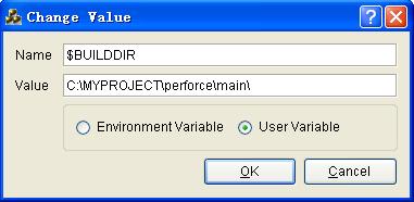
Variable Name:
The name by which you will refer to the variable in your build process. In a nod you reference the variable as follows, eg. $BUILDDIR.
Make Available as Environment Variable
Variables can be made available as environment variables to applications that are executed by R2build.
Persistent
The variable value will be saved between R2build executions. also will be saved when you save the build project.
(Tips: use "-" to remove a variable in the variable window)
Use Variables
see the previous screen shot, both environment variable and user variable can be used in node config parameter, with a $ sign before the var name. For environment variable, it will be used as node running env.
Run
your build project
Run without debug: Click “Run” button in the
application toolbar, the current build project will run, all the log will be
displayed in the log window (at the same time save to $ BUILDLOGFILENAME ).
Run with debug: Click “Run Debug” button in the
application toolbar, the current build project will run in debug mode, it will
break on the breakpoint.
Run from current node: right on the node, a menu will popup, choose "run from current node" , the build will be executed starting from this node
Set/remove breakpoints: To set a breakpoint, first select
one node and then click the “Add breakpoint” button in the application toolbar.
To remove a breakpoint, first select the node with breakpoint and then click “Remove
breakpoint”. You also can remove all the break points from the current build
project by clicking “Remove all breakpoints” in the application toolbar.
Setup
nightly build
1.
add new project, and change the schdule parameter for current project (see R2build dashboard for more detail)
2. Create Scheduled
Tasks in windows(without dashboard)
Command line
options: R2build
supports command line options, the format is:
R2Build.exe [-r][-q] [buildfilename]
-r means run the build project file
-q means quit R2build after the build finished
buildfilename is the full path name of the .r2p file(build project file)
You can setup nightly build task by these command line options.
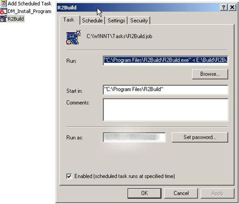
In Control panel->Scheduled tasks->Add
scheduled task, in the wizard, select the R2Build.exe, and input the parameter
required. After the wizard closed, double click the new created tasks called “R2build”,
modify the “run” parameter to "C:\Program
Files\R2Build\R2Build.exe" -r E:\Build\R2Build.r2p
Modify the italic part according to your
settings.
R2build Dashboard
Basic introduction:
the dashboard show the latest build of all projects chart in "All Projects: Latest build summary", this chart indicate how many project's latest build is successful or fail..
for one specific project, you can select it in the project list, all the builds summary chart of current project is shown in "Your Project Name: All Builds" , the log window show the log info of the latest build, select the all builds tab you can see the detail info of all builds. Also the project's configuration info is displayed on the top section.
Funtions of R2build Dashboard
- New button: create new build project
-Add Button: add a new project, input the r2p file, also the schedule info
-Open Button: edit the current select project
-Remove: remove the current build project from the project list(the build .r2p file and the log files will not be deleted)
-Run Button: run the current selected build project now.
-enable/disable schedule: enable or disable build schedule for current selected project
-Refresh Button: reload all the log information
-keep dashboard run, it will start the build according to the schedule info. CLOSE Dashboard will not monitor the build and trigger the build. (Dashboard check every project's next build time every two seconds, if it's time to build , it will lanuch the build, so please don't close dashboard)
What should i do when i open the .r2p file created by previous version of R2build?
There is some difference when you open the old verion of .r2p.
1. the icon size changed in R2build 2.0, so your build flowgraph maybe does not looks very nice, you can adjust it manully.
2. In old version of R2build, there is no On failure tab, so all the build flowgraph will be put on "Main" build flowgraph, you can run it without any adjustment. But to make your main build flowgraph clean, you can try to modify your main build flowgraph, move the error handling nodes to "On Failure" build flowgraph. at the same time you should setup the "Fail condtion" in the general tab of node parameter dialog. (By defalut, for the old version of .r2p, R2build 2.0 will use "ignore errors for current node" to provide the comptiblity for the previous version) .
Advanced topic: Extend R2build, add more plugins
R2build uses xml file to describe the Node UI dialog and the related parameter. To support a new tool/application in R2build, you should check the command console parameter of this new application, then create a new xml file in the $R2buildInstallDir/plugins, When R2build start, it will scan all the plugin config xml file, and build the corresponding nodes in the toolbox. This xml describes the console parameter, it’s also called application description xml.
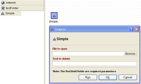
A simple example
Let’s start from a very simple example. You get a new application, simple.exe, by calling simple.exe –h , you know simple.exe have two parameter:
Simple.exe –f filename –x text
-f filename: file to open
-x text: text to delete from file.
To add simple.exe into R2build toolbox, you need create a simple.xml into the $R2BuildInstallDir/Plugins, you can create your own folder, and put simple.xml into that folder. The following is the xml file:
<?xml version='1.0' encoding='utf-8'?>
<Plugin version='1'
group="" name="Simple" appName="Simple"
description="">
<Type>command</Type>
- a command console application
<Executor>simple.exe</Executor>
- the application’s executable file name
<FixedParameter></FixedParameter> -Fixed parameter
<SubExecutor></SubExecutor> -the sub executor of this application
<Icon>simple.png</Icon> -the icon file of this application
<ParameterConfigUI>
- the main config section
<FileBrowser display="File to open" BrowseDir="FALSE"
Filter="" type="Parameter" relatedParameter="-f
"></FileBrowser>
-first parameter
<LineEdit display="Text to delete" type="Parameter" relatedParameter="-x"></LineEdit> -the second parameter
</ParameterConfigUI>
<ReturnValues> -enum return values of this application
<ReturnValue name="Yes" Condition="$RETURN!=0"></ReturnValue>
<ReturnValue name="No" Condition="$RETURN==0"></ReturnValue>
</ReturnValues>
</Plugin>
Will show in R2build as the following screenshot:
Structure
of the xml file
<Plugin>
<Type>command</Type>
//Type is the plugin type, values are : command/plugin
<Executor>cleartool.exe</Executor>
//provide the executor file name, for comamand plugin, it's command's executable file, for plugin,it's plugin's .dll file name in the same dir of this file
<FixedParameter></FixedParameter>
//provide the requeired and non-configrable parameters
<SubExecutor>update</SubExecutor>
//The sub-command of this plugin, some of the tool
support sub-command, for example cleartool.exe has a sub-command update
<Icon>Update Snapshot View.png</Icon>
//The icon of this plugin
<ParameterConfigUI>
//The section for describing the plugin parameter
dialog and the related plugin parameterA list of Config items…
<ComboBox display="this is a combox sample"
relatedParameter="-d">availableValue="selectionA;selectionB;selectionC" value="selectionA"></ ComboBox >
<LineEdit display="UserName and password(seperate by
',')" type="Parameter" relatedParameter="-Y"></LineEdit>
<FileBrowser display="Sourcesafe Database " BrowseDir="TRUE"
Filter="srcsafe.ini" type="Env" relatedParameter="SSDIR"></FileBrowser>
……
……
……
</ParameterConfigUI>
<ReturnValues> //the possible return values for this plugin
<ReturnValue name="Success" Condition="$RETURN==0"></ReturnValue>
<ReturnValue name="Fail" Condition="$RETURN!=0"></ReturnValue>
</ReturnValues>
</Plugin>
Supported ParameterConfigUI Items
The following table list all the supported ParameterConfigUI Items. The xml attributes of any item is composed by “Common Attribute” + “Specific Atrribute”.
Config UI item |
Description |
Specific attribute for this UI Item(see “common attribute” for attribute that’s applicable for all items) |
|
ComboBox |
show many items in ComboBox, and let user select one availableValue: list all the available values in the listbox, seperated by ; |
availableValue |
list all the available displayed values in the listbox, seperated by ; between values |
InternalValue |
The internal value is the real value that will apply in the command, seperated by ; between values |
||
ListBox |
show multiple items, and let user select more |
availableValue |
list all the available values in the listbox, seperated by ; between values |
selectionMode |
:single,multi,extended |
||
InputBox: |
show input box, and let user input the parameter directly |
|
|
RadioGroupBox |
show radio groups |
checkable |
If checkable is TRUE, put a check box in the group box to enable /disable the whole group |
layout |
The layout for the child of this RadioGroupBox. If it’s 1, means we have one column, 2 means 2 columns |
||
value |
The default value for checkable |
||
RadioBox |
show selection item in radio button groups, and let user select one of them |
|
|
LineEdit |
show multiple line editor, let user input multiple lines as parameter |
isPasswordBox |
If this lineedit is a password edit, the value is TRUE or FALSE, if it’s a password box, will show mask while inputing |
CheckBox |
show check box, and let user check/uncheck some parameter |
|
|
FileBrowser |
show the open file/dir dialog to let user select a file or dir, have the following attrs |
BroserDir |
if this file browser is a Dir Broswer(TRUE) or File browser(FALSE), all upper case |
Filter |
the filter for this filebrowser, correct format "Images (*.png *.xpm *.jpg);;Text files (*.txt);;XML files (*.xml)"” |
||
VarViewBox |
show all the defined variables |
|
|
TabView |
Show the tab view |
CurrentPage |
the current page of the tab |
TabViewItem |
Show one tab |
|
|
ParameterConfigUI Item common attributes
Each Config UI Item has the following common attributes
display: This label(display) for this item
type: see” Supported ParameterConfigUI Item Type”
relatedParameter: the related parameter for this config item
ParaSeperator: parameter seperator for this config item, will add seperator between the relatedParameter and the value, if not config there is no seperator between para flag and values . for example -i"c:\aaa.txt" the paraSepeter is comma , -i c:\aaa.txt , the paraSepetra is one space
Required: if this field is a required parameter, values are : TRUE or FALSE (all upper case) , TRUE means this parameter is required. Default value is TRUE if not setting.
Supported ParameterConfigUI Item Type
For each Config UI Item, they should belongs to the following types
Group: this config ui item is the used to hold other config ui items
ExecutorParameter: the parameter for the main executor,this config ui item is used to get the values for command parameter, the releatedParamter field show it's releated parameter
Parameter: the parameter for the sub executor,this config ui item is used to get the values for command parameter, the releatedParamter field show it's releated parameter
Env: this config ui item is used to set the values for enviorenment variable, the relatedParameter field is the env variable name. NOTE: Env variable will be passed to the command as working envirment variables.
Property: this config ui item is used to get the other property of the command, the releatedParameter field is the property name. The supported property is
WorkingFolder( the folder where this command is working)
More examples
See $R2buildInstallDir/Plugins for more examples.